January 8, 2016
36 view(s)
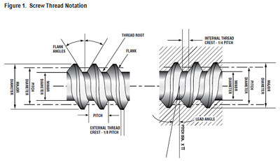
Terms Relating to Screw Threads and Gages
The following terms are essential to understanding screw threads and thread gages. https://www.threadcheck.com/terms-relating-to-screw-threads-and-gages/technicalinfo/ Thread Plug Gage- is a complete internal thread gage of either single or double-end type, comprising handle and threaded gaging member or members, with suitable locking means.
Thread Ring Gage- is an external thread gage employed for the size control of threaded work. American Gage Design – AGD style thread ring gages are adjustable with screws integrated within the gage body. Solid style ring gages are not adjustable and are more popular among international standards. Both styles of gages have their advantages and disadvantages.
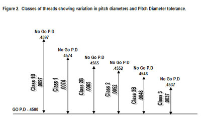
Terms Relating to Classification and Tolerances
1. Allowance- An intentional difference in the dimension of mating parts. It is the minimum clearance or the maximum interference which is intended between mating parts. It represents the condition of the tightest permissible fit, or the largest male member mated with the smallest female members. Example: One-half inch, Class 1, American National Coarse thread series: Minimum pitch diameter of nut…………………………………………………………………………………………...0.4500 Maximum pitch diameter of screw……………………………………………………………………………………….0.4478 Allowance (positive)……………………………………………………………………………………………………….0.0022 One-half inch, Class 4, American National Coarse thread series: Minimum pitch diameter of nut…………………………………………………………………………………………..0.4500 Maximum pitch diameter of screw……………………………………………………………………………………….0.4504 Allowance (negative)……………………………………………………………………………………………………...0.0004 2. Tolerance- The tolerance on a dimension is the total permissible variation in its size. The tolerance is the difference between the limits of size. Example: One-half inch screw, Class 1, American National Coarse thread series: Maximum pitch diameter …………………………………………………………………………………………………0.4478 Minimum pitch diameter ………………………………………………………………………………………………….0.4404 Tolerance ………………………………………………………………………………………………………………….0.0074 3. Basic Size- The theoretical or nominal standard size from which all variations are made. 4. Crest Clearance- Defined on a screw form as the space between the crest of a thread and the root of its mating thread. 5. Finish- The character of the surface on a screw thread or other product. 6. Fit- The relation between two mating parts with reference to the conditions of assembly. The quality of fit is dependent upon both the relative size and finish of the mating parts. 7. Neutral Zone - A positive allowance. (See “Allowance.”) 8. Limits- The extreme permissible dimensions of a part. Example: One-half inch screw, Class 1, American National Coarse thread series: Maximum pitch diameter 0.4478 THESE ARE Minimum pitch diameter 0.4404 THE LIMITSSymbols for Basic Dimensions
For use in formulas for expressing relations of screw threads, and for use on drawings and for similar purposes, the following symbols should be used: Major diameter ………………………………………………………………………………………………D Corresponding radius ……………………………………………………………………………………….d Pitch Diameter ……………………………………………………………………………………………….E Corresponding radius ……………………………………………………………………………………….e Minor Diameter ………………………………………………………………………………………………K Corresponding radius ……………………………………………………………………………………….k Angle of Thread ……………………………………………………………………………………………..A One-half angle of thread ……………………………………………………………………………………a Number of turns per inch …………………………………………………………………………………...N Number of threads per inch ………………………………………………………………………………...n Lead ……………………………………………………………………………………………………..L = 1 / N Pitch or thread interval ……………………………………………………………………………....……p = 1 / n Helix Angle ……………………………………………………………………………………………….. s Tangent of helix angle ……………………………………………………………………S = L / 3.14159xE Width or basic flat at top, crest, or root …………………………………………………………………..F Depth of basic truncation …………………………………………………………………………………..f Depth of sharp V thread ……………………………………………………………………………………H Depth of American National and Unified forms of thread ………………………………………………h Length of Engagement ……………………………………………………………………………………..Q Included angle of taper ……………………………………………………………………………………..Y One-half included angle of taper …………………………………………………………………………..ySymbols for Wire Measurements
Measurement over wire …………………………………………………………………………………….M Diameter if wire ……………………………………………………………………………………………...G Corresponding radius ……………………………………………………………………………………….g The method of designating a screw thread by means of symbols is by the use of the initial letters of the thread series, preceded by the diameter in inches (or the screw number) and number of threads per inch, all Arabic numerals. If the thread is left-hand, the symbol “LH” shall follow the class of thread. No symbol is used to distinguish right-hand threads. For screw threads of American National and Unified form, but of special diameters, pitches, and lengths of engagement, the symbol “NS” or “UNS” is used. Please contact Thread Check Inc. with any questions or requirements that you may have regarding thread gages and technical specifications. Thread Check Inc. 900 Marconi Ave. Ronkonkoma, New York 11779 631 231 1515 [email protected] www.threadcheck.com